|
To get the ball rolling we designed and constructed two of our own "company" robots. The robots we made are not meant to be the best design for the ultimate boxing robot. We wanted to build a couple examples of this class of fighting robot with the least amount of work in the shop.
We used a lot of water-jet cutting and a standard BattleKits base to keep the build time down. Another time-saver was the use of several off-the-shelf extruded aluminum square tubes in the arms, legs, and hips. Almost all the components are available from either McMaster-Carr or BattleKits.
These robots put up a good fight but a different design from a clever builder should be able to spank these things. Keep in mind that this is not the only way to build a robot! You are welcomed to use any part of our design that you like but our purpose in posting this is to help you use our experience to come up with a new, different, and hopefully better design.
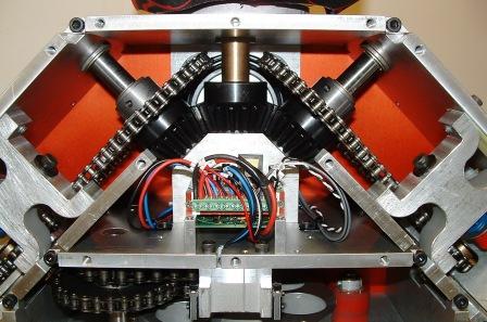
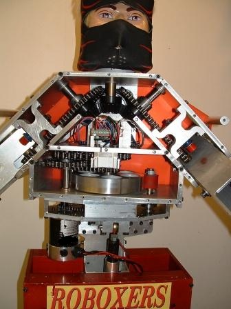 This picture shows most of the tricky parts of the robot. We used an all-electric design to keep things simple. This picture shows most of the tricky parts of the robot. We used an all-electric design to keep things simple.
To get a sense of scale, note that the hips are 15 inches wide and the sprockets in the upper chest are 5 inches in diameter. The robot stands just over four feet tall.
The upper body is divided into four distinct areas, each of which houses components that provide a different function. Below are descriptions of each area.
|
|
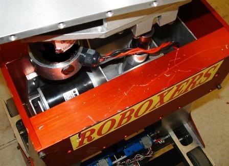
Starting from the lowest level, here we see the electric linear actuator that flexes the robot's hinged spine. Most of the actuator is hidden inside the robot's "shorts". We used a Motion Systems actuator that has a unique and very useful clutch that disengages at the ends of the travel. This eliminates the need for limit switches and it also lets you use full power right to the ends of the travel without damaging anything. When the actuator reaches the end of the travel it simply stops while the motor continues spinning. This same type of actuator was used in another one of our robots - BattleBots champion BioHazard.
We liked the idea of disengaging the motor at the ends of the travel so much that we also used it in our punching mechanism, (details below).
|
|
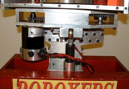
This picture shows the single electric motor that powers all the punching action. We used the A28-150 AmpFlow motor for its light weight and extreme power. The motor power goes through a two-stage speed reducer made from #25 chain and sprockets. The speed reducer has a heavy-duty design using 3/8" thick aluminum plates because it serves triple duty as 1) a speed reducer, 2) a mounting point for the spine hinge and linear actuator, and 3) a mounting point for a 7/8" central shaft, (not visible in this view), on which the rest of the upper body is mounted.
Keep in mind that the central shaft is fixed in place and does not turn, yet there are a total of six power transmission elements either fixed to the shaft with keys or riding on bearings on the shaft, (four sprockets, one gear, and one friction wheel). The shaft is keyed to the body of the speed reducer and it runs all the way up into the head. It does not turn but all the power of the motor is ultimately transmitted through that shaft. How is that possible? Details below.
|
|
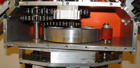
After the power passes through the two-stage reducer it goes into this section of the torso. In order to get realistic punching power from our single electric motor, we felt it was important to come up with a design that would enable us to use full power right to the ends of travel. Here is a view of the mechanism we came up with.
The power from the motor goes into the little red urethane drive wheel on the right. It presses very hard on a big aluminum friction wheel that has a flat spot on it. The aluminum wheel makes only one rotation when the robot throws a punch. When the flat spot reaches the red drive wheel it disengages and the drive wheel and motor spin freely without jamming up the mechanism.
This set-up also does double-duty as a torque limiting device. If the arms get jammed, the urethane wheel slips and the motor will not stall.
The aluminum friction wheel spins freely on the central shaft. The motion from the wheel then goes through another three-stage speed reducer that is made from #35 and #40 sprockets and chains. The large sprocket in the final stage of this speed reducer is keyed to the central shaft.
Not only does the friction wheel spin freely on the central shaft; the entire torso above the first two-stage speed reducer also pivots on that shaft. This has the effect of rotating the upper body left and right by 25 degrees each way as the friction wheel rotates one revolution. When the robot throws a left punch, for example, the shoulders and upper body rotates left to get maximum power behind the punch with very human-like motion.
The red drive wheel is fixed to a shaft that passes through a curved slot in the aluminum plate. The slot and the flat spot on the friction wheel are visible in the above picture if you look closely. The only thing holding the upper and lower sections together is that central shaft. The head is also keyed to that non-rotating shaft so it always points forward. The robot always "looks" at his opponent even as his arms are swinging and his chest and shoulders are pivoting back and forth. This is another design element that adds realism to the action.
|
|
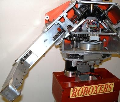
The same motor that pivots the torso also powers both arms. Take a look at the above picture to see how this is done. The central shaft continues up through this section of the chest. Since the upper body moves relative to this fixed shaft, it is possible to pick up that motion and use it to drive the arms.
Three large bevel gears take that motion and send it off at an angle that gets it to the shoulder joints. The central bevel gear is fixed to the non-rotating shaft with keys. The other two bevel gears pivot around the fixed gear in a planetary motion as they move with the pivoting torso. A large sprocket transfers the resulting rotation to smaller sprockets in the shoulders.
Also visible in this view are some electronics that, (among other things), flash a strobe on the top of the head when the robot is struck. The central shaft is hollow and some of these wires pass right through the shaft to get into the head and down into the lower body without the possibility of getting mashed in the gears and chains. Thanks to teammate Dave Andres for his work on the electronics.
Inside the "H" shaped blocks are 2" long springs that absorb the arm's momentum at the end of the travel. Only a short length of the springs protrude from the blocks. The springs are kept in place with urethane bumpers that are screwed on to shoulder screws that pass through the springs.
|
|
The sprocket in the shoulder joint is fixed to the upper arm so the whole upper arm rotates along with the sprocket. The final step in this convoluted path of power transmission is getting the forearm to move. That is done with one last set of sprockets and a chain, (visible in the elbow area). The number of teeth in all the sprockets was carefully chosen to provide the correct range of motion in every joint.
There are a total of six stages of speed reduction, (and torque multiplication), to get the 6000 RPM of the motor down to a reasonable punching speed. The final gear ratio is 183 to one. Ignoring the slowing effects of friction and inertia, this works out to about four punches per second.
When one arm extends to throw a punch, the other arm retracts. The chest and shoulders pivot in the direction of the punch while the head keeps looking forward. One motor actuates the pivoting chest, both shoulders, and both elbows, while the other motor in the linear actuator flexes the spine to aim the punches up and down. That is a lot of motion from just two motors. We did it this way to keep things simple, reduce the build time, and make controlling the robot easier. Good robot builders will find ways of using additional motors and possibly pneumatics to make more powerful and effective boxing robots.
|
|
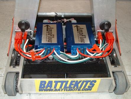
Here is a view of the rolling platform. It's a standard BattleKits base. One of the keys to getting this all to work is to put as much weight as possible into the base. The robots are tall and if they get too top-heavy they will have a tendency to tip over. The components in the base include four AmpFlow E30-150 motors, Two AmpFlow motor controllers, and four 13Ah batteries. Everything is connectorized using Anderson connectors.
|
|
|